Power Factor

POWER FACTOR OPTIMIZATION
In the vast majority of Industries, and facilities like Hotels Hospitals, Commercial Stores, etc. There are a large number of electric motors in:
- Pumping Equipment
- Ventilation
- Air conditioning
- Air Compressed
- Specialized manufacturing processes, etc.
IMPORTANCE OF PF
These motors consume a large amount of reactive p that they use to produce magnetic fields, which are their working principle.
This reactive p is not used to produce work, however, it must be present for the operation of motors and other equipment that use electromagnetism to operate, such as transformers, ballasts, etc.
Reactive p also has to be generated and transmitted from the generating plants to the users, so it is necessary to consider it in the sizing of these plants, cables, transformers, etc.
Therefore, since there is a low PF in a building or facility, it is more expensive for the supply company to feed that excess reactive p required, so a penalty is applied when this PF value is less than 90%.
P=Power
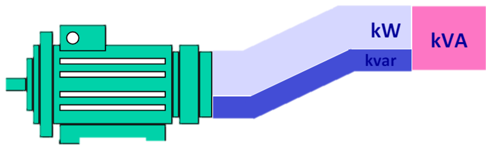
WHAT IS THE POWER FACTOR?
It is the proportion of apparent power that we use to produce a job, so we can say that:
It is the way to measure the Productivity of a
electrical installation but not efficiency.
Generally, the Power Factor is defined by the power triangle, which is the representation of any load or electrical system that has inductive elements.
What Causes a Low PF?
In the vast majority of electrical installations, there is a large amount of equipment, driven by:
- Electric induction motors
- Water pumps
- Ventilation
- Air conditioning
- Conveyor belts
- Air compressors
- Mills
- Machinery
- Specialized manufacturing processes, etc.
These induction motors consume a large amount of reactive energy to generate magnetic fields, in order to induce movement in the shaft of the motor, i.e., this reactive energy is necessary for the operation of the electric motor.

Excess reactive energy consumption results in a low Power Factor.
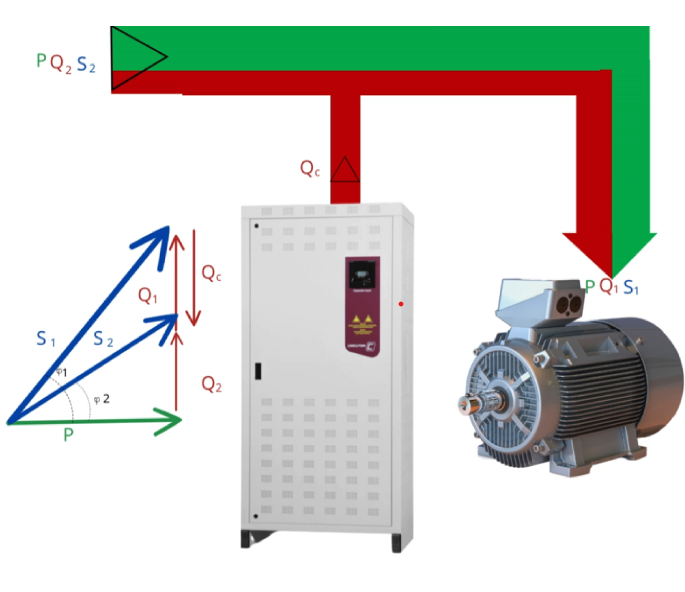
P: Active Power
Q1: Reactive P (Before Compensation)
S1: Apparent P (Before Compensation)
Q2: Compensated Reactive P
S2: Compensated Apparent P
Qc: Capacitive P
Cos θ 1<1
Cos θ 2 ≈ 1
The Capacitor Banks store the flow of Reactive energy (Q1), creating a “negative” component (Qc) on the abscissa axis of the power triangle, and therefore, reducing the value of the reactive component (Q2). and approximating the power factor (Cos θ) to 1.
P=Power
Power Demand
The constant increase in energy requirements, both in the industrial sector and in the domestic sector, and the high investment needs that this implies; They make us look for ways to reduce these consumptions, since it is more economical to save energy than to invest to generate these kW and kWh.
Therefore, we can say that the cheapest kW or kWh is the one that is not consumed.
One way to achieve this is by controlling or rather managing the demand for electrical power.
It is the sum of the powers of the electrical equipment or devices that are connected at a given instant.
What to do for the PF Correction
We perform analyses in the electrical system for the correction and compensation of the PF, electrical measurements are made with specialized meters to monitor and graph the behavior of active, reactive and apparent energy. As well as, voltage, current, and power quality.
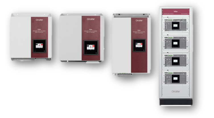


Capacitor Banks
Once the survey and measurements have been carried out, the most suitable capacitor bank is determined to correct the power factor to the desired value, normally we recommend obtaining a power factor of 95% to 98%.
Harmonic Filters
It is also important to evaluate the quality of the power in the different transformers and load centers, in case it is necessary to recommend a harmonic filter to prevent them from being present in the electrical network and generating any type of disturbance or damage to the electrical equipment.
Power Factor Bonus
You can get a bonus from suplier by increasing the Power Factor.
In the way that we evaluate the benefit-cost ratio for the selection of the capacitor bank and that allows it to be a profitable project.
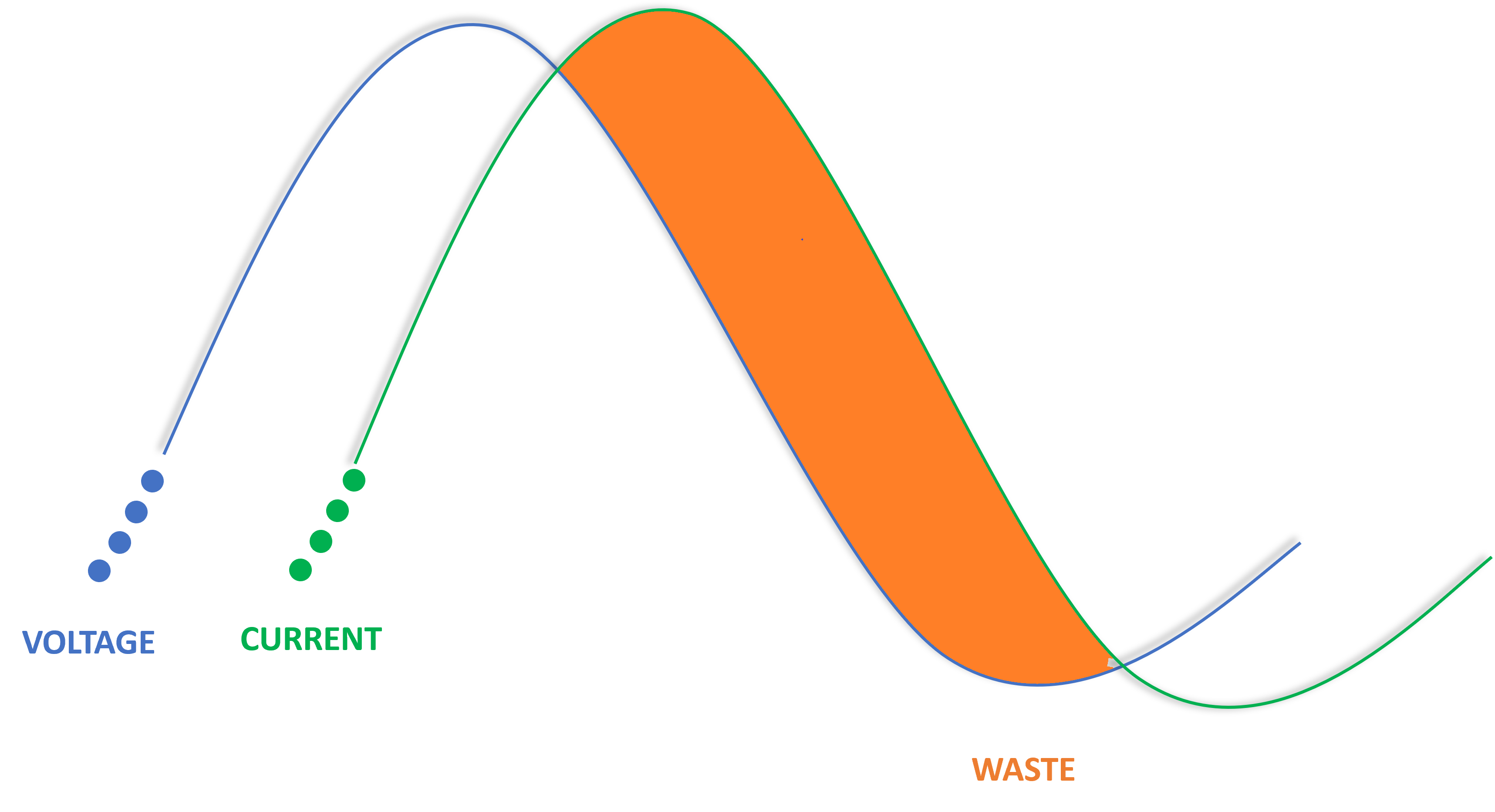
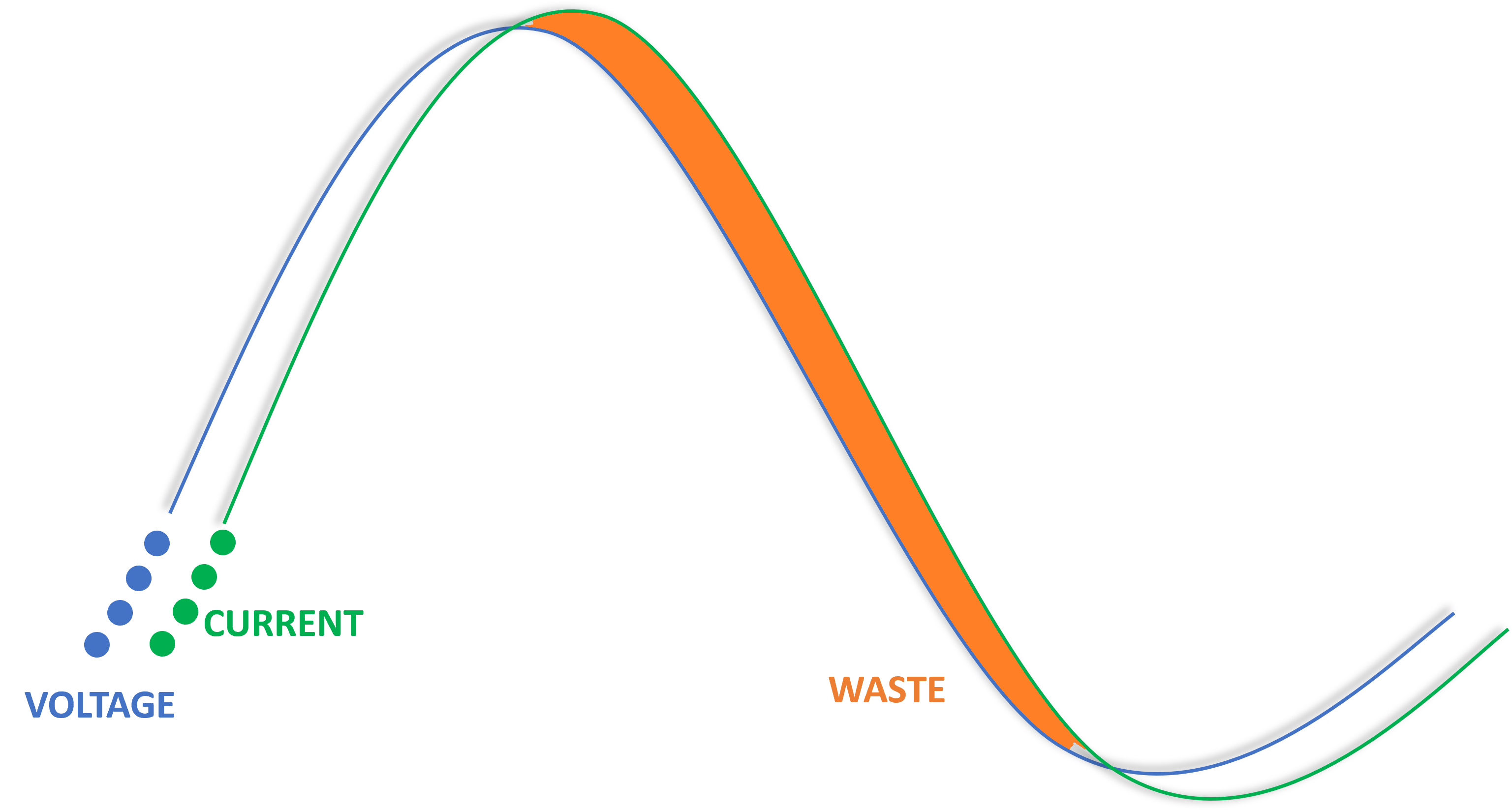
BEFORE POWER FACTOR CORRECTION
LAG BETWEEN VOLTAGE & CURRENT CREATES WASTE
AFTER POWER FACTOR CORRECTION
WASTEFUL LAG IS REDUCES TO INCREASE ENERGY EFFICIENCY
CHECK LIST CORRECTION PF
Information required to perform a detailed analysis and size.

- History of 12 months of electricity billing, detailing all the parameters of consumption, demands, -power factor (We request the updated electricity bill).
- One-line diagram (indicating number of transformers, voltages in the secondary).
- Electrical measurements on each transformer to evaluate the behavior profile of Voltage, Power, PF and Harmonics.
- Available space to place the capacitor banks. To determine distances between the point of interconnection and its placement.
- Location of the Facility (City and Address).
Benefits of Increasing The PF
•Eliminate Penalties for Low PF
•Discount on the Electricity Bill.
•Reduction of Energy Losses in the Electrical System.
•Voltage Regulation in the Electrical System.
•Load Release for Transformers (Release kVA).